Client:
Quantity:
Size:
Application:
What it is
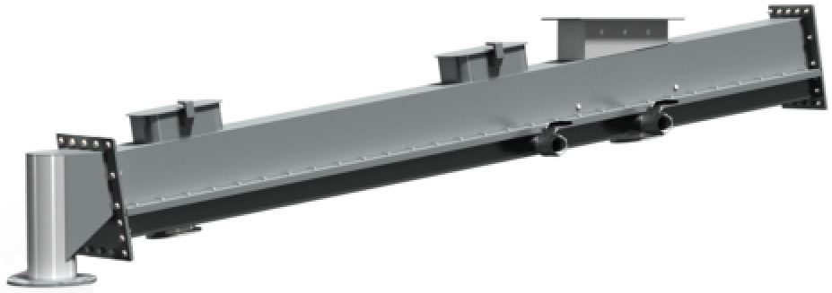
An air-gravity conveyor is a device for moving a variety of light-weight, fluidizable dry bulk powders. The conveyor consists of a rectangular chamber separated by an air-permeable, porous media. The media is placed along a horizontal plane to separate two chambers within the conveyor: An upper chamber to handle the material being conveyed, and a lower chamber to handle compressed air.
Air-gravity conveyors are typically manufactured in 10 ft | 3 m sections. Shorter sections are used to make up the exact required length of the total conveyor.
When installed, an air-gravity conveyor is sloped slightly downward – normally at 6 – 8° from horizontal. A benefit to air-gravity conveying is that the length of an air-gravity conveyor is limited only by available headroom versus headroom needed to accommodate the unit's slope. Hypothetically, an air-gravity conveyor can be infinitely long – if the required headroom is available. In fact, air-gravity conveyors with lengths of 200 – 300 ft | 61 – 91 m are not uncommon.
How they Work
A positive fan or blower injects low pressure, dry air (typically 1 psig | 0.7 bar) into the lower chamber. The air permeates upward through the porous media. When the air is counterbalanced by gravity, a conveyor uses physics similar to an air hockey table to fluidize/aerate materials as they flow downstream through the conveyor's upper chamber.
Materials Handled
Air-gravity conveyors are used to handle a variety of dry, light-weight, easily fluidized powders, such as activated carbon, alumina, bentonite, calcium carbonate, cement, clays, detergent powders, fly ash, gypsum, lime, pulverized ores, silica sand, soda ash and talc, among others. To evaluate whether a powder is well-suited for air-gravity conveyance, a general rule of thumb is that the particle size is normally smaller than 50 mesh.
Industry Comparison: Air-Gravity Conveying Equipment
Several equipment manufacturers supply air-gravity conveyors; however, deficiencies may exist across product designs. Taking the time to pre-qualify the design quality of an air-gravity conveyor will pay significant dividends.
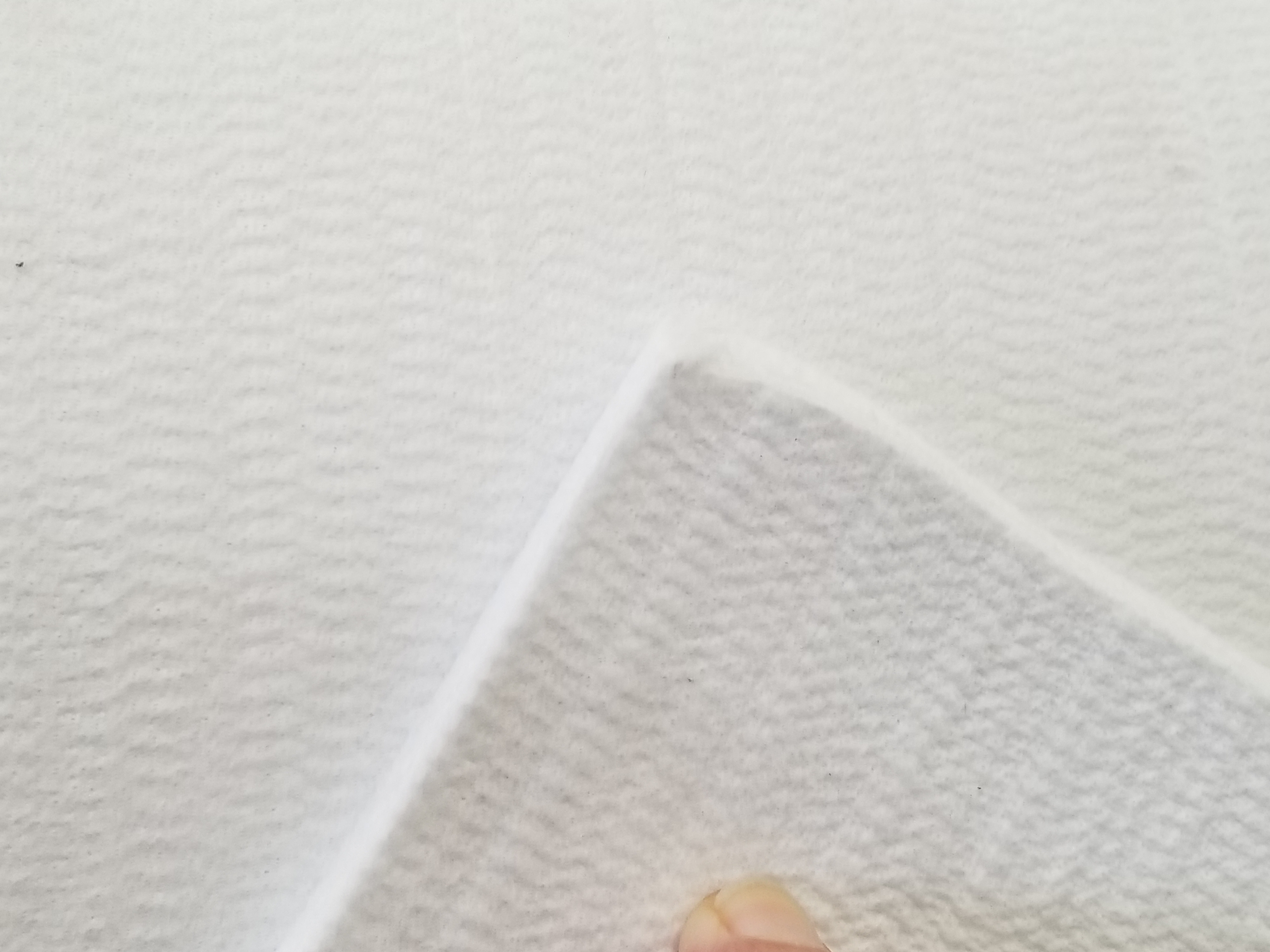
Media material (Figure 1)
Many manufacturers utilize a woven material. A primary concern for woven materials is that they require stretching, prior to and during installation. Also during installation, woven materials can be easily cut or have holes punched in them. In any case, woven materials are prone to unraveling and fraying, which can cause conveying inefficiencies and necessitate frequent media replacement. Problems exist with woven materials in that they require stretching prior to installation, and unravel when cut or punched.
For added durability, the Vortex Aero-Slide™ Conveyor instead utilizes a superior material: non-woven, needled polyester.
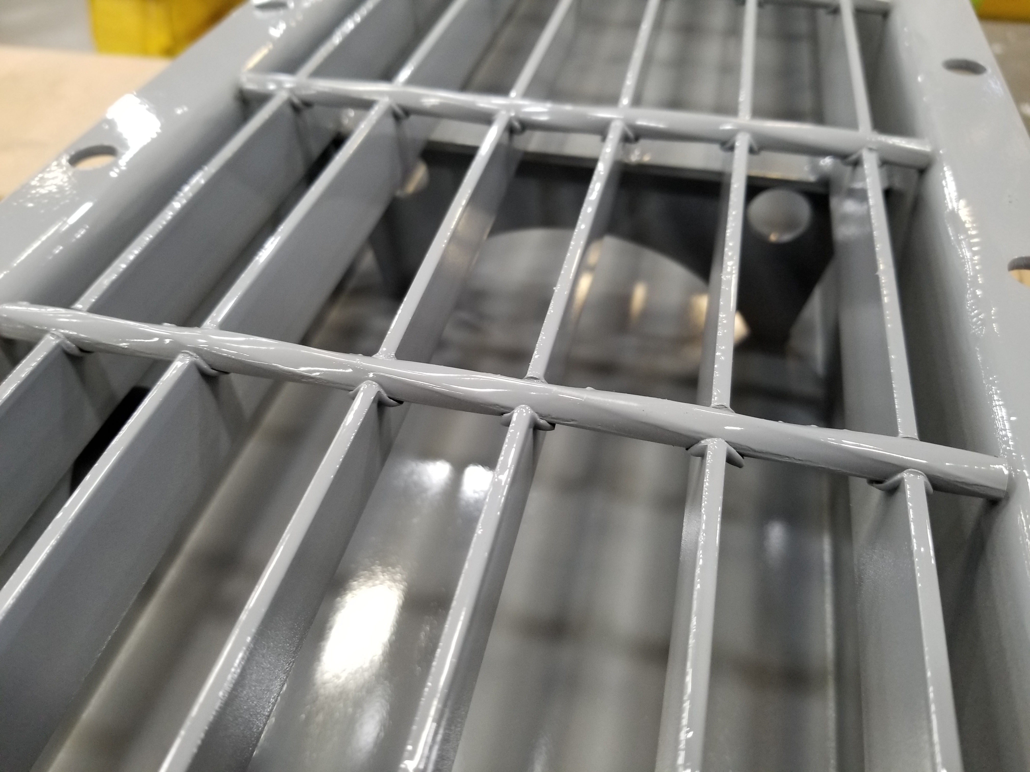
Media support bars (Figure 2)
Some manufacturers utilize random cross bars or flimsy screens for support beneath the media. In these cases, the media will tend to sag over time – creating pockets that can trap product and create conveying inefficiencies.
For enhanced durability and media support, the Vortex Aero-Slide™ Conveyor instead utilizes a steel grate. The grate is constructed from equally spaced, intersecting support bars which run parallel and perpendicular to the conveyor.
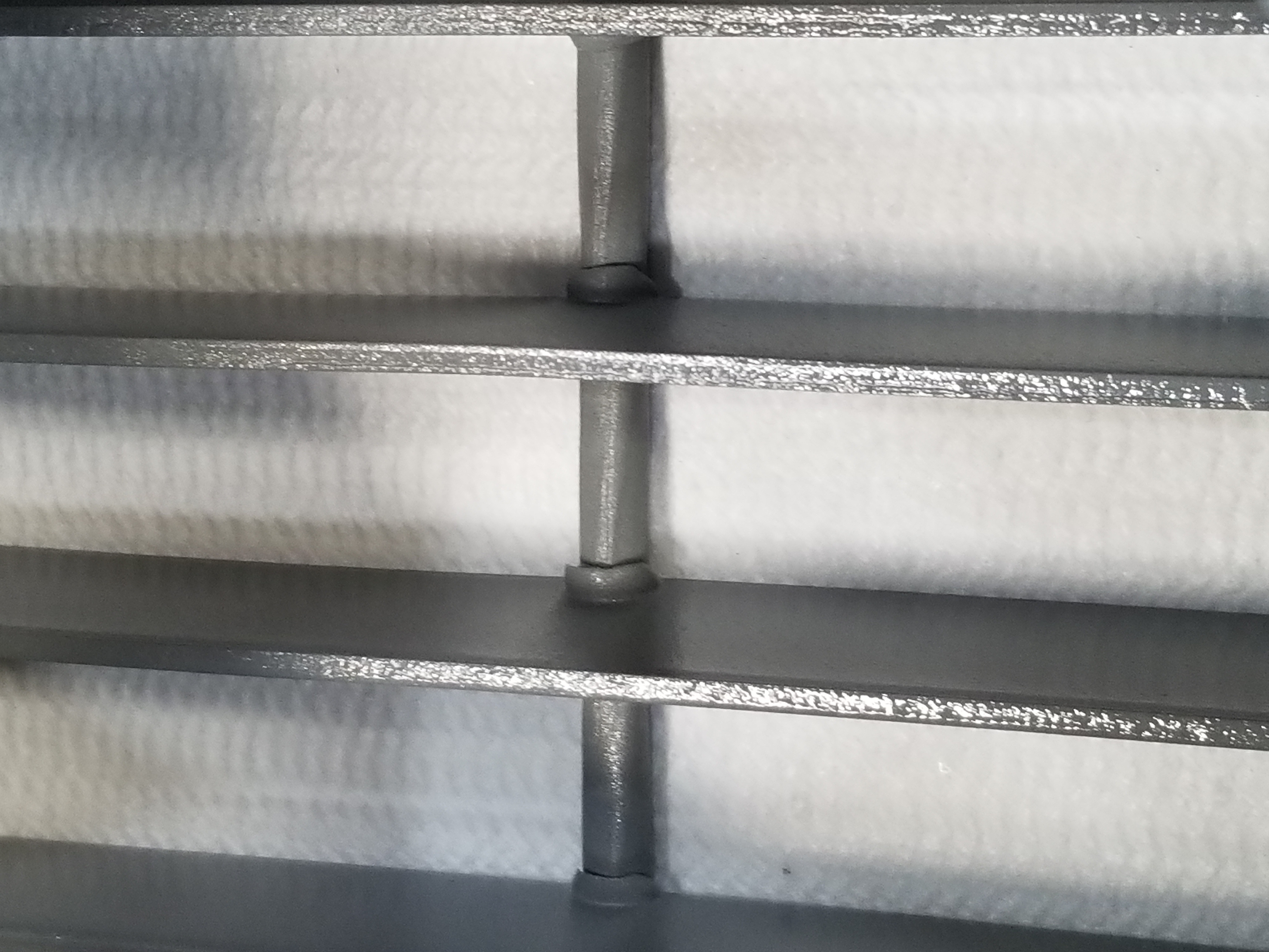
Media coverage (Figure 3)
The media material should span the full length and width of the conveyor, so that it completely covers the horizontal area between the upper and lower chambers. If any gaps exist, air may create an air column in the top chamber that may create material pile-up and blockage within the system.
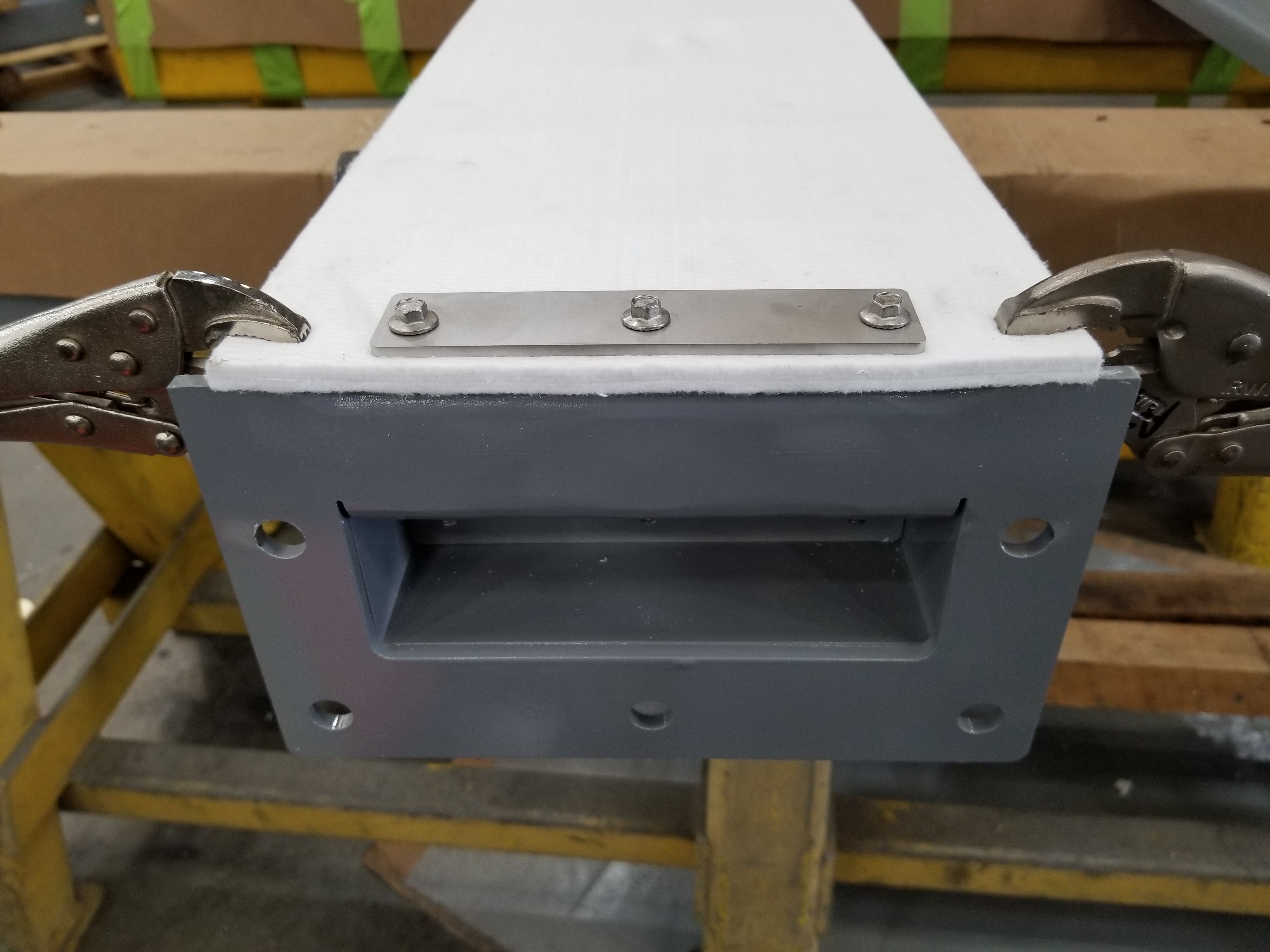
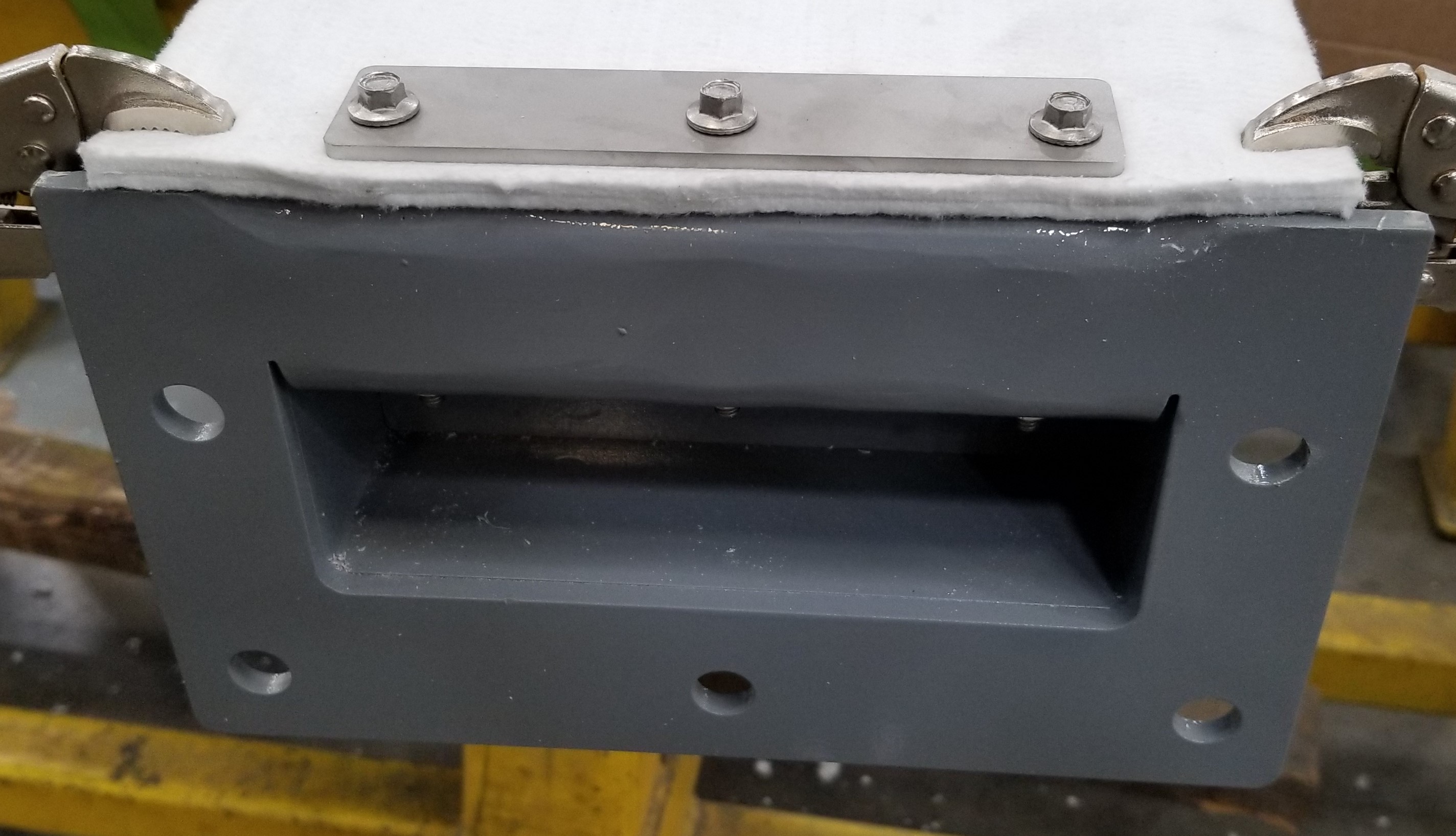
Media retainer bars (Figure 4)
At the ends of each section of an air-gravity conveyor, media retainer bars ensure the media stays firmly in place. To fasten the media retainer bars, some manufacturers utilize pop rivets. Pop rivets tend to break over time, creating an air path issue within the conveyor.
For added durability, the Vortex Aero-Slide™ Conveyor instead uses bolts to fasten the media retainer bars at each end of the air chamber.
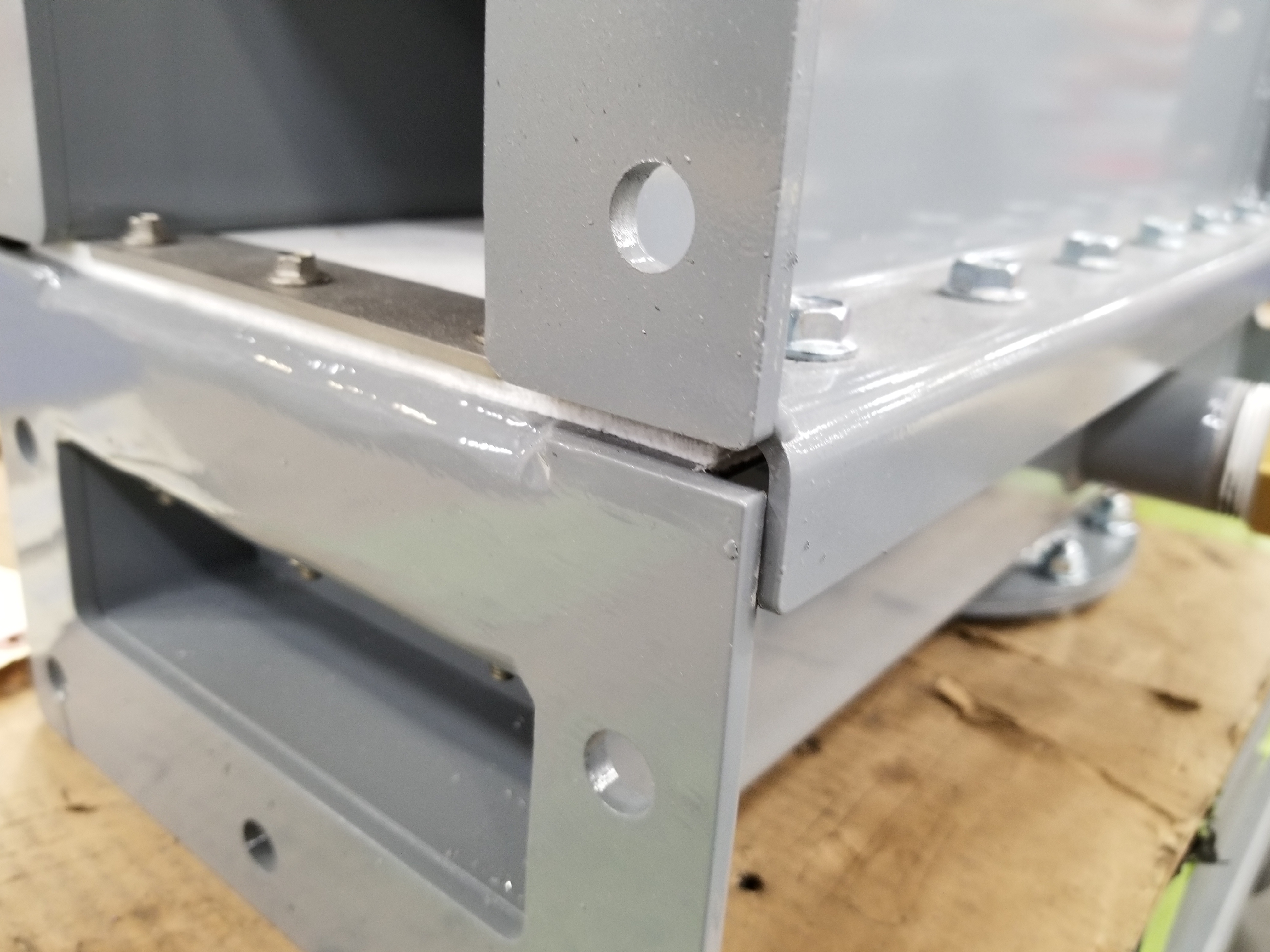
Rain ledges (Figure 5)
The unit should contain a rain ledge. Rain ledge construction is such that the side flanges of the upper chamber overlap the side flanges of the lower chamber. This greatly helps in keeping the media material dry – especially in outdoor applications.
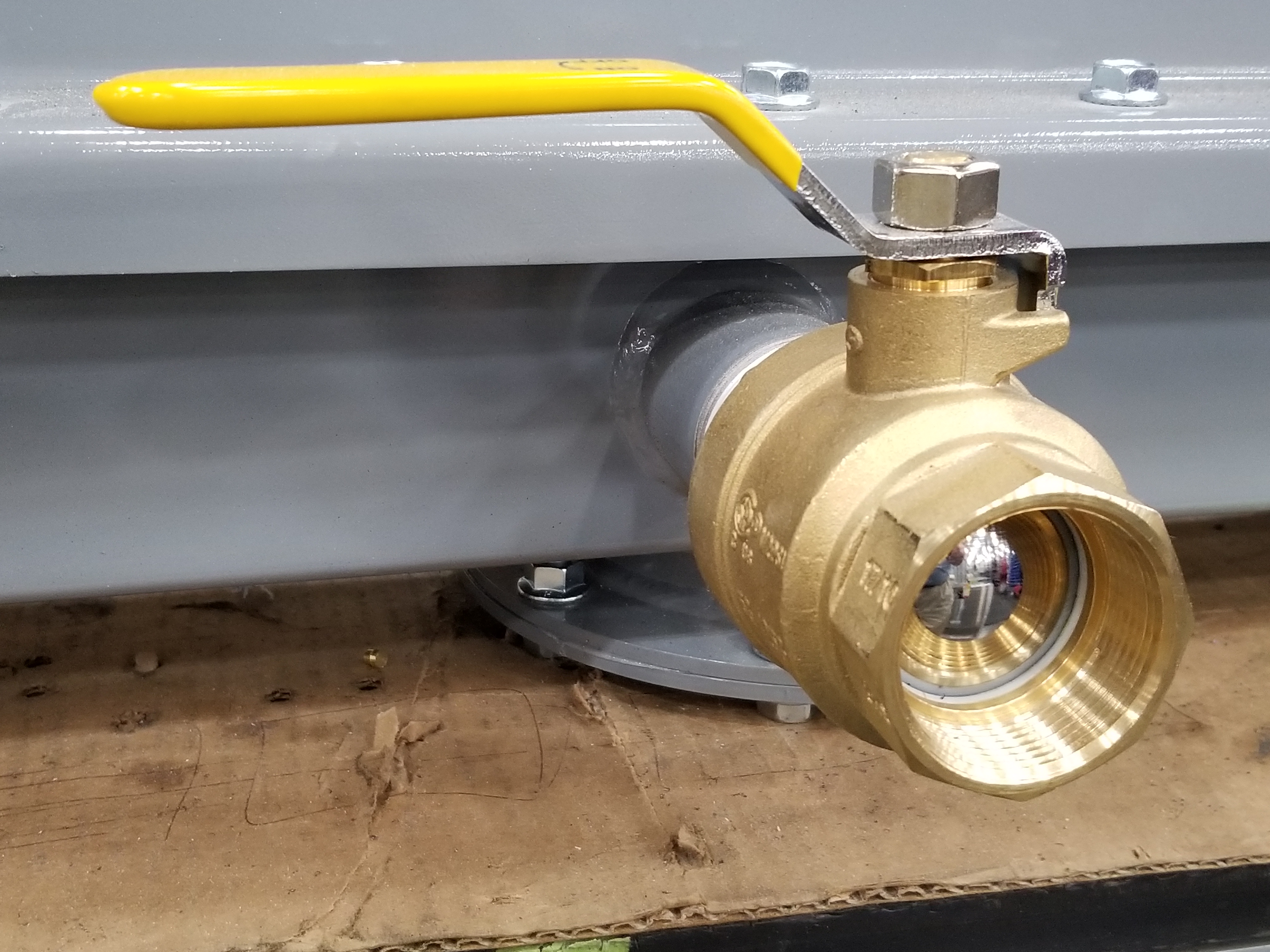
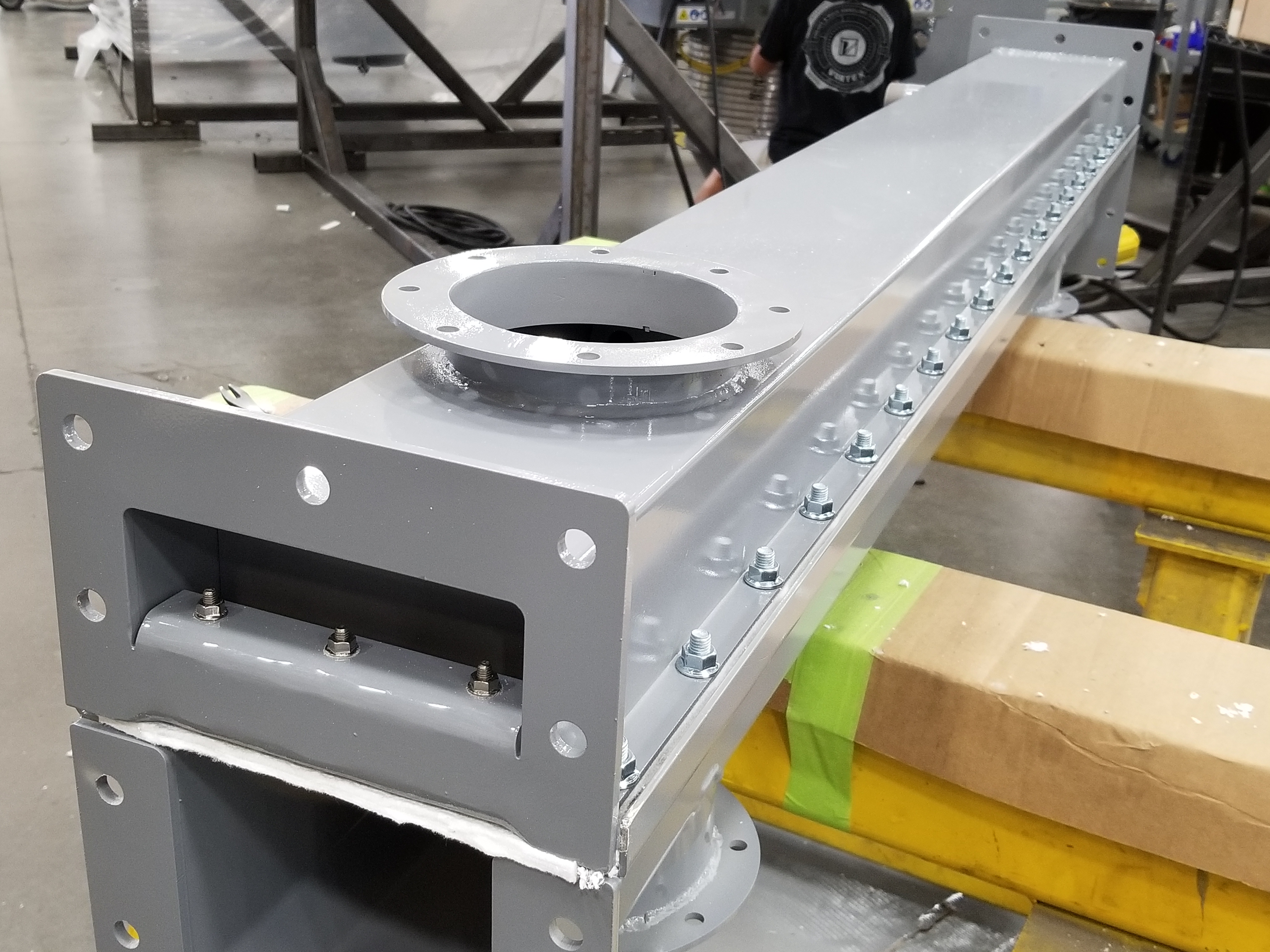
Inlet ports (Figure 6)
An inlet port is required within each section of the unit, to introduce air into the lower chamber for product transport. The port valves are used to adjust the amount of air being introduced.
Inspection ports (Figure 7)
Each section of the conveyor should contain an inspection port, should internal, visual inspection become necessary.
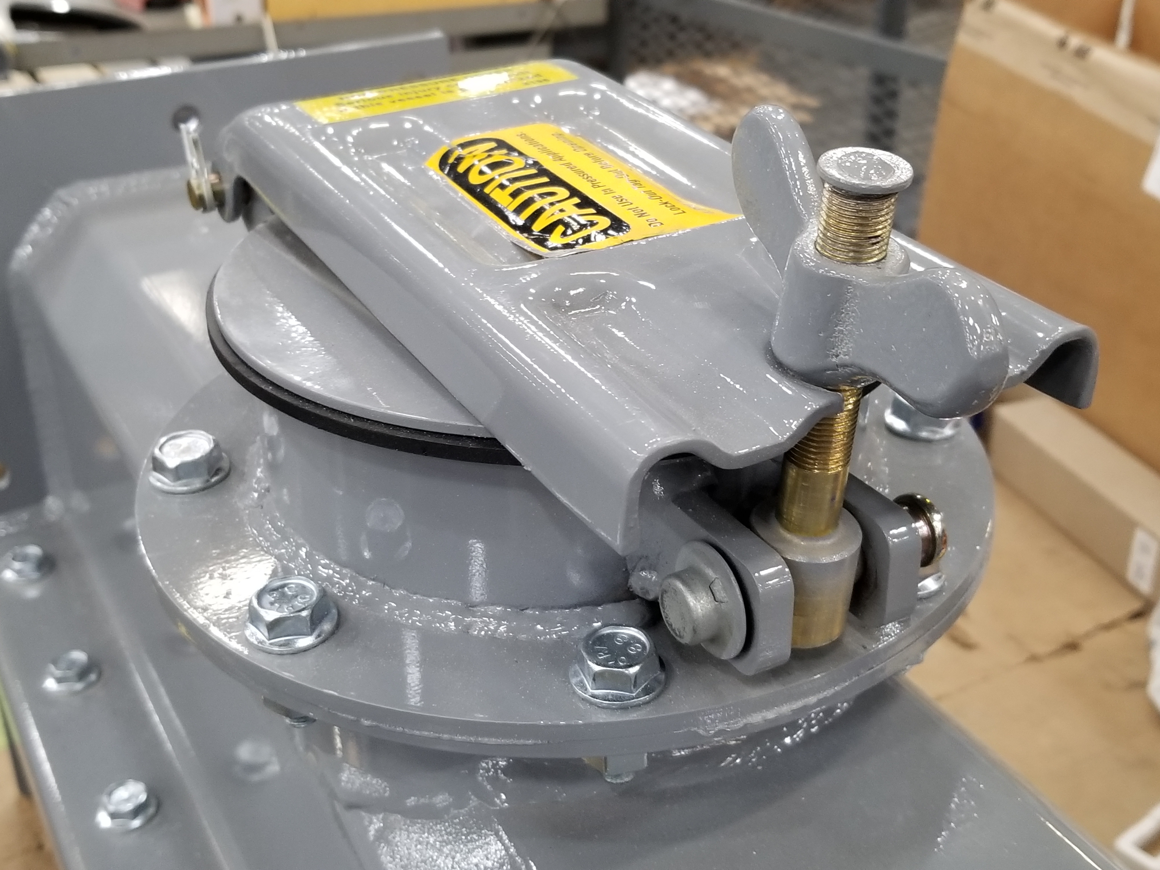
Clean-out ports (Figure 8)
Each section of the conveyor should contain a clean-out port at the bottom of the conveyor, in case product needs to be removed when maintenance is required.
Economic Advantages of Air-Gravity Conveyors:
- Cost-effective
- Simple installation
- No moving parts (reduce wear, spare parts & prolongs service life)
- Minimal maintenance requirements
- Low energy consumption (low-pressure air)
- Requires a single power source (fan or blower)
- No damage to product handled (reduce waste)
- Increased conveying capacities
Environmental Advantages of Air-Gravity Conveyors:
- Dust-tight to atmosphere
- Low energy consumption
- Low noise levels (fan or blower is remote from the conveyor)
Safety Advantages of Air-Gravity Conveyors:
- No moving parts (lessens operator safety risks)
- Low noise levels (fan or blower is remote from the conveyor)
- Dust-tight to atmosphere (prevent health & safety hazards)
Other Air-Gravity Conveyor Considerations:
One must also realize that with any type of conveying system, disadvantages may exist – and air-gravity conveyors are no exception.
The following instances may create blockage within the system:
- If the moisture content of the material handled is too high, the materials may become too heavy to be properly fluidized.
- If the air entering the lower chamber is too moist, it may combine with the material being handled or create clogs in the media’s pores.
- Occasionally, overnight temperature drops may create condensation within the system. If product is introduced with this moisture present, blockages may result.
- If the installation angle of the conveyor is not steep enough, blockages may result.
System Options:
- Turn Boxes: Used to divert product flow.
- Side Discharges: Allow materials to be diverted toward other processes between the beginning and end of an air-gravity conveyor.
- Slide Gates or Drum Valves: Used to shut off and regulate material flow through the upper chamber.
- Dust Collection Vent: Mounted at the end of the conveyor to collect fugitive dust.
- Bin or Filter: In order to convey materials through an air-gravity conveyor, air is introduced and contained within the system. At some point, this air must be properly vented through a bin or filter within the system.
A systems analyst can advise if any of these options should be considered for a particular air-gravity conveying system.
Vortex Air-Gravity Conveyors
Among their equipment offerings, Vortex also manufactures air-gravity conveyors, known as the Vortex Aero-Slide™ Conveyor. Typical sizes range from 6 – 24 in | 152 – 610 mm. Vortex works closely with systems groups and engineering firms worldwide to design Aero-Slide™ Conveyors which fulfill every requirement of a client’s specific application.