
Client:
Quantity:
Size:
Application:
As published in World Cement
By Kevin R. Peterson
Introduction
Behind only water, concrete is the second most consumed substance in the world. Cement, one of the main ingredients of concrete, is produced worldwide, with China, India, and the US being listed as the top three producers. Production figures for 2017 reveal that China produces 2.4 billion metric tonnes per year (tpy), India 270 million metric tpy, and the US 86 million metric tpy.
Currently, there are 104 cement plants located in 34 US states. These plants manufacture and ship cement, typically by rail car, to 362 US cement terminals, where the cement is loaded into containerised trucks that are destined for their local customer base. One can only imagine just how many plants and terminal facilities exist worldwide.
Typically, a loading spout is utilised as part of the cement loading process. When considering the purchase and use of a loading spout, being cognisant of certain product features can be the difference between utter frustration with failing tools or well-designed equipment that provides reliable operation with favourable life cycle costs.
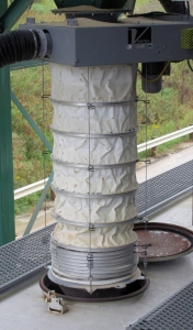
External Sleeve
One of the main advantages of a loading spout is the ability to deposit cement directly into the rail car or truck opening, without the worry of cement dust escaping into the atmosphere along the pathway between the holding bin and the transport vehicle. Fixed hoppers, chutes, or socks do not offer this protection.
With the loading spout, a flexible external sleeve encompasses the material pathway. The sleeve extends and retracts with the spout, once it is correctly positioned above the loading hatch. Sleeves are available in a variety of materials, which are chosen to address the compatibility and service conditions of the material handled. The sleeve protects both the material from the environment and the environment from the material.
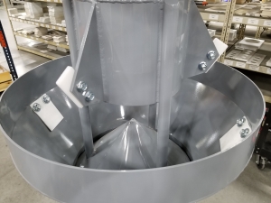
Stacking Cones
Within the sleeve, material flows through stacking cones, which are typically made of various grades of abrasion-resistant steel, stainless steel, or polymer. It is important to ensure that they are properly matched to the type of material being handled and its abrasiveness.
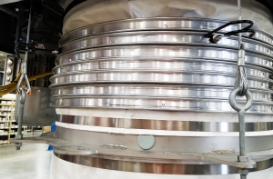
Support Rings
Support rings ensure the straight, even stacking of the retracted sleeve. Typically, an inner sleeve ring and an outer sleeve ring will be bound together at selected intervals, trapping the sleeve fabric between them. Many spout manufacturers drill through the rings and sleeve to bind the rings together with blind rivets. This practice can result in contamination of the product, if a rivet should break. Since the sleeve material has been penetrated, it can also facilitate tearing or damage to the sleeve material over time. Plant managers should consider a spout that utilises support rings clamped on the sleeve, rather than riveted together.
Self-Sealing Discharge
A self-sealing discharge can be added to a spout. This is particularly useful in applications where it is desirous to keep fine material within the confines of the spout while it is retracted from the loading hatch of the transport vehicle. As the spout scavenger seats into the open hatch, the self-sealing discharge's interior mechanism, called a dispersing cone, continues to extend into the interior of the transport vehicle. This action unseats the dispersing cone, allowing material to flow freely through the scavenger. Upon loading completion, the dispersing cone retracts and the seal is once again created as the spout retracts out of the loading hatch.
Cable Lifting System
The majority of loading spouts on the market today offer a two- or three-cable lifting system. With these systems, major problems occur if a cable breaks due to excessive wear, or if a cable is damaged due to a transport vehicle moving prior to the spout being retracted. In either case, unexpected downtime is created for both the supplier and the transporter, as the spout cannot be operated until maintenance personnel fix the broken cable.
A four-cable spout provides better stability. If one cable was to sustain damage, the spout could still be operated until there is sufficient time to repair the damaged cable. The result is that maintenance can be performed at a more opportune time.
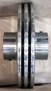
Cable Lift Pulleys
Cable pulleys are the culprit of many spout maintenance issues. The typical lift pulley contains a ‘sharp’ edge and, as the cable spools in and out of the pulley, that sharp edge creates premature wear to the individual wires of the cable. Over time, the cable will eventually wear through and break.
Another common issue with lift pulleys concerns the width of the pulley opening. If the width is not sized exactly to the diameter of the wire cable, the cable will wind onto the pulley instead of overlapping itself, becoming bound between the previous cable wrap and the side of the pulley. This creates additional wear to the cable; and more importantly, it creates slack within the cable – the technical term for which is backlashing – as the spout is lowered and the cable unwinds from the pulley. The slackened cable has a propensity to ‘jump’ the confines of the pulley before wrapping around the pulley shaft. If this should happen, the loading process must be suspended until the cable is freed from the shaft.
Cable pulleys that are correctly sized and machined with radius edges are essential for optimum spout reliability.
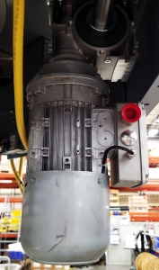
Drive Motor
It is important to make sure that the drive motor that operates the hoist system contains a braking system. Without this feature, the lifting cables have a tendency to become slack while the spout is being extended into place. Backlashing can also occur, which causes the cable to ‘jump’ the pulley and become wrapped around the pulley shaft. Once again, this creates additional maintenance issues.
Some companies offer the motor brake as a standard component, while others consider this to be optional equipment. However, this feature should not be overlooked when considering a new spout or a spout replacement.
Dust Collector vs. Filter
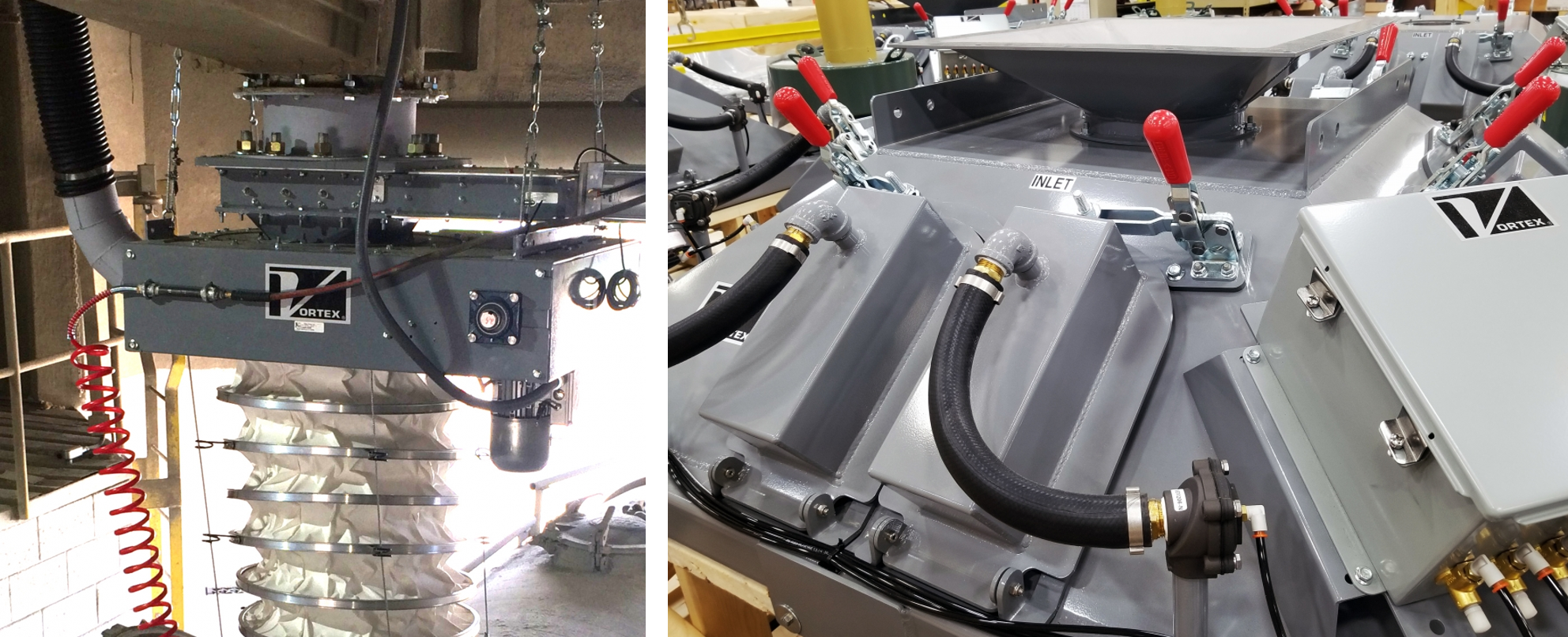
In addition to environmental concerns, studies have confirmed a correlation between exposure to cement dust and the health of employees involved in the cement industry. Respiratory issues, including asthma, bronchitis, and pneumoconiosis, are linked to cement dust, as well as eye and skin irritation. Not only does cement dust that travels the pathway between a holding bin and the transport vehicle need to be contained; the dust created at the point of entry into the transport vehicle must also be captured and eliminated from the plant environment. This process can be accomplished by means of a dust collector or filter.
Most spouts are designed with a clean air centrifugal fan, which is used to create negative air suction. This draws the dust created at the loading point up through the spout via the open area between the cones and the outer sleeve, to be collected at the main frame. The main frame of the spout contains an outlet connection where the dust can be exhausted to a dust collection system and later removed. In this manner, dust created during the loading process is evacuated from the loading area.
Some spout manufacturers offer a dust filter system. Instead of using a dust collector to gather and get rid of the dust, a filter located above the spout temporarily captures the dust drawn upwards through the spout. High-pressure compressed air is periodically used to purge the captured dusts and deposit them back into the material flow stream. The dust is re-entrained back into the load and sold as product, which adds profitability to the process.
Other Features
While the elements presented above are the main features of loading spouts, there are also other features available. Those include:
- Tilt Probes – These signal that the vessel is filled to the desired level and can trigger an automatic raise feature.
- Discharge Skirt – Flexible rubber strips that help to contain fugitive dust in an open loading configuration.
- Vibrator – This helps to clean residual dust lodged within the spout before the spout is retracted.
- Pendants – A hand-held device that allows remote control over spout operations.
- Spout Positioner – A separate piece of equipment installed above the spout. It allows for positioning of the spout without having to reposition the transport vehicle.
Taking that bit of extra time to review and understand the features of a loading spout will pay significant dividends in the future.