


Client:
Quantity:
Size:
Application:
When designing systems for the handling of dry bulk materials, such as cement, it is important to consider the challenges associated with the material being handled and how to plan for future maintenance. Maintenance of these systems can be costly, time consuming, and dirty. Manufacturers of these systems must consider several key principles. These include: minimising wear and abrasion to limit maintenance, decreasing production downtime, and extending product service life.
By sourcing and implementing products that can be both repaired and maintained in-line without being removed from the system, the consumer will benefit by saving in both upfront and future costs in terms of repairs and production downtime.
Loading spouts
Loading spouts provide fast and steady material flow during the loading of dry bulk materials such as cement into open and/or enclosed trucks, railcars, or stockpiles. When equipped with proper components, a loading system can be designed to capture fugitive dust, prevent material waste, ensure plant and environmental safety, and require minimal maintenance.
Loading systems are placed under an immense amount of pressure by the materials they handle. Problems, such as cable fraying can naturally occur from wear and tear. To eliminate cable fraying, a loading spout can be equipped with an CNC-machined three-piece pulley with rounded edges and precision cable grooves. This design eliminates cable failure and other costly downtime for cable repair.
Many traditional spouts utilise eyebolts to guide the sleeve support rings during spout extension/retraction. The primary disadvantage of the eyebolts is their maintainability. If either the lifting cables or the outer sleeve need to be replaced, the eyebolts must either be removed from the sleeve or physically distorted (opened) to free the sleeve from the lifting cables.
To solve this maintainability issue, a spout can incorporate four spiral-shaped cable guides along the circumference of each outer support ring. The main advantage of spiral guides over eyebolts is that the lifting cables and/or the outer sleeve can be removed without having to manipulate the spiral guides. The lifting cables can be extracted from the spiral guides while the guides stay connected to the sleeve support rings.
Most loading spouts feature a two or three-cable design. If one cable of a two or three-cable spout should break from wear or premature trucker pull away, it is inoperable until a repair is made. Vortex Global’s four-cable lifting design provides stability and more lifting torque compared with some standard loading spouts. Should one cable on the Vortex four-cable spout break, the spout can be raised and lowered for maintenance, but it should be taken out of operation until the cable is replaced.
A cable can be easily replaced in the specially machined pocket within the Vortex drive hub.
Loading spout filtration systems
Spout filtration systems are engineered to capture the fugitive dust emitted from the spouts and deposit it back into the material flow during the loading process, eliminating material loss. These filtration systems are more cost-effective than central dust collection systems and offer in-line maintenance features. Magnehelic® pressure gauges provide differential pressure readings. When high differential pressure is indicated, filter cartridge maintenance or replacement is needed.
Filtration systems that feature hinged panels secured by a handled, stationary clamping mechanism help accelerate the inspection and maintenance processes and allow interior access without tools.
Loading spout positioners
Positioners are used in conjunction with standard volume loading spouts to facilitate and speed up the loading of open or enclosed trucks and railcars at loadout stations.
Internally vented spout positioners allow for dust control during the loading process. While the hopper and spout remain attached to the positioner, hopper seal replacement can be easily performed to limit downtime.
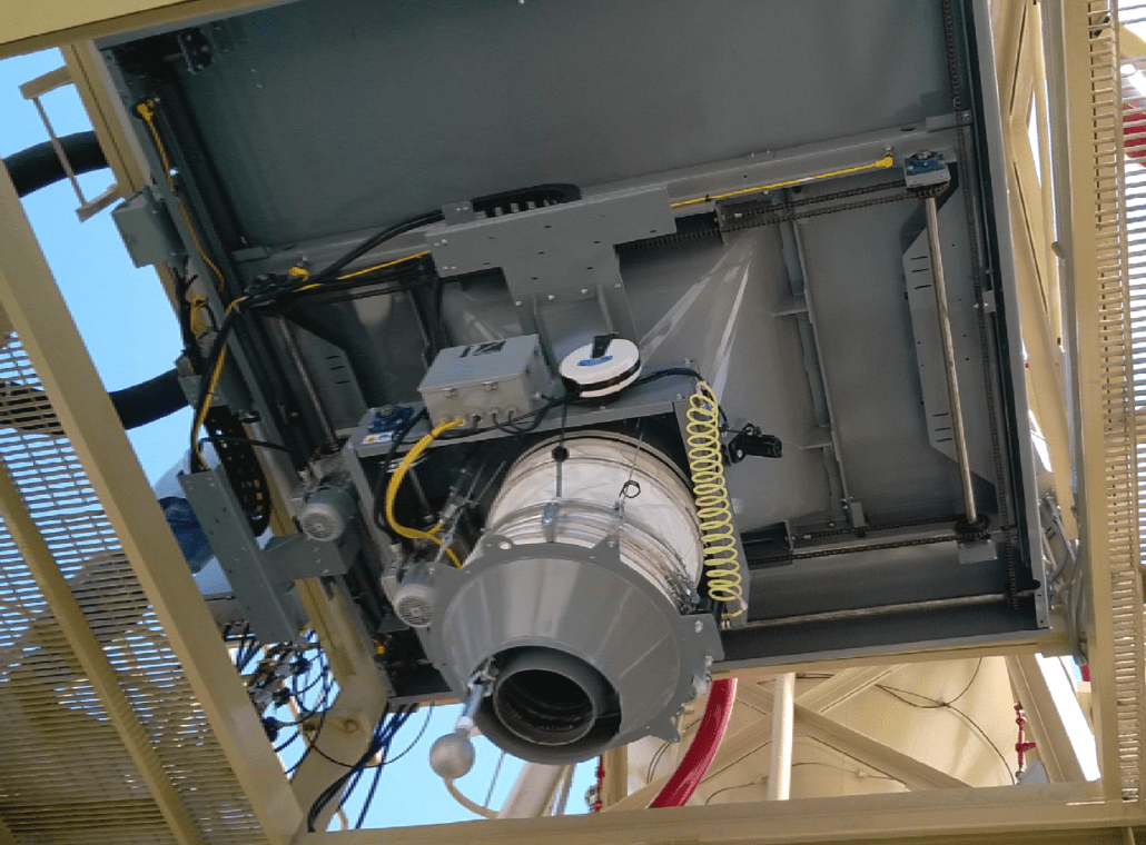
Case study: loading spout with dual axis positioner handling cement
In this truck loadout application, a cement plant in Arizona sourced a Vortex Loading Spout and Dual-Axis Spout Positioner to assist in their application.
This spout features a 14 in. (355 mm) outlet scavenger. The positioner is capable of positioning 1 ft (305 mm) front-to-back and side-to-side above a truck. The system also features an internal vent-through hopper that contains two hopper assemblies: one for materials handled, and one for dust. The hoppers include maintenance-friendly seals that can be replaced without disassembling the positioner.
Case study: loading spout, filtration system and positioner assist at coal refinery
This coal refinery ordered a Vortex Loading Spout, Spout Positioner, and Filtration System to assist in processing waste coal and turning it into a clean carbon fuel.
The telescoping loading spout is equipped with a four-cable hoist system and CNC machined cable pulleys for less spout maintenance.
The dual-axis spout positioner allows a 2 ft (610 mm) spout movement along the X and the Y axis so trucks need not reposition during the loading process.
An in-line filter traps dust created during the loading and re-introduces it back into the load making for an environmentally friendly loading process.
Aerated conveying systems
Aeration systems are designed to convey dusty, powdery, or flaky materials by using gravity on a downward slope. They can be installed on the inside bottom of a storage container or mounted to follow a specific path inside the plant. Products typically included in aeration systems are aerated conveyor systems, aerated bin bottoms, and aerated trough systems. Aeration systems can be custom designed and manufactured to individual project specifications so they can handle any material and desired flow rate.
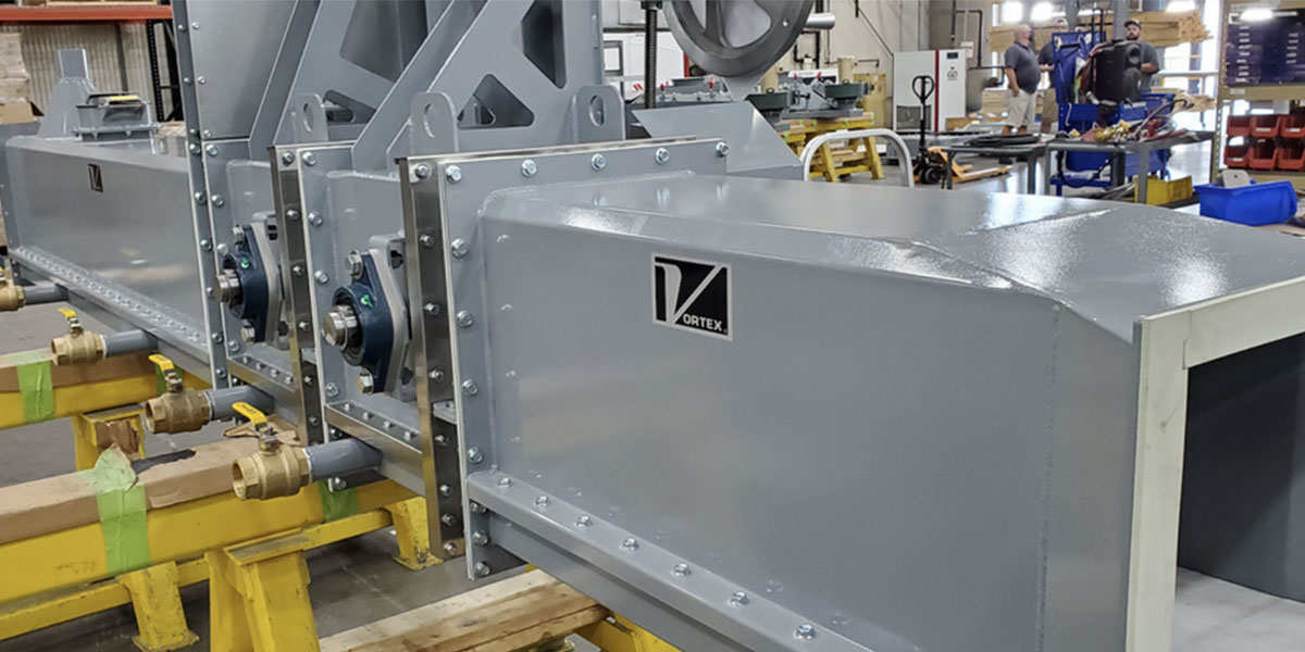
Conveyor
Aero-Slide Conveyors consist of a rectangular shaped convey line which is horizontally separated by an air-permeable, porous media to create an upper and lower chamber. To encourage material flow, the conveyor is installed at a slight downward slope – typically 6 – 8 ̊ from horizontal. In the upper chamber, handled materials are transferred along the porous media.
Through the lower chamber, a fan or blower injects low pressure, dry air – typically 1 psig | 6.9 kPa. As air is pumped into the lower chamber, it permeates upward through the porous media. When counterbalanced by gravity, the air-gravity conveyor uses physics similar to an air hockey table to fluidise/aerate handled materials as they flow downstream through the upper chamber. Once materials are transferred downstream, the excess air is vented through a system bin or filter.
Aero-Slide conveyors feature several maintenance friendly features. Among these are clean out ports, which allow for the inspection of product in the lower air chamber and maintenance, if necessary. Each section of the conveyor has a clean out port, located along the bottom of the lower air chamber. Additionally, there are no moving parts other than the blower, leading to increased operator safety, reduced wear and prolonged service life.
Gate valve
The Aero-Slide gate valve is specifically designed to be used in tandem with the Aero-Slide conveyor. Designed much like a conventional roller-supported slide gate, the gate valve features a vertical-mounted blade with a downward closing stroke. While the gate valve can be used for metering, it is primarily intended to shut-off material flow. Depending on application, the gate valve can either be installed within the convey line or beneath the silo discharge, at the conveyor’s inlet. Its narrow profile allows for limited space installations.
Drum valve
The Aero-Slide drum valve is a self-contained unit that prevents material packing, dusting to atmosphere and other valve failures. This valve is specifically designed to be used in tandem with the Aero-Slide conveyor. Unlike the Aero-Slide gate valve, which is primarily intended for material shut-off, the Aero-Slide drum valve is well-suited for metering material flow.
The drum valve features a rotating, cylindrical blade with a V-notched bore. This provides for more precise metering control. Additional advantages of the valve include its ability to shut-off or meter flow and the fact that it is dust-tight to atmosphere.
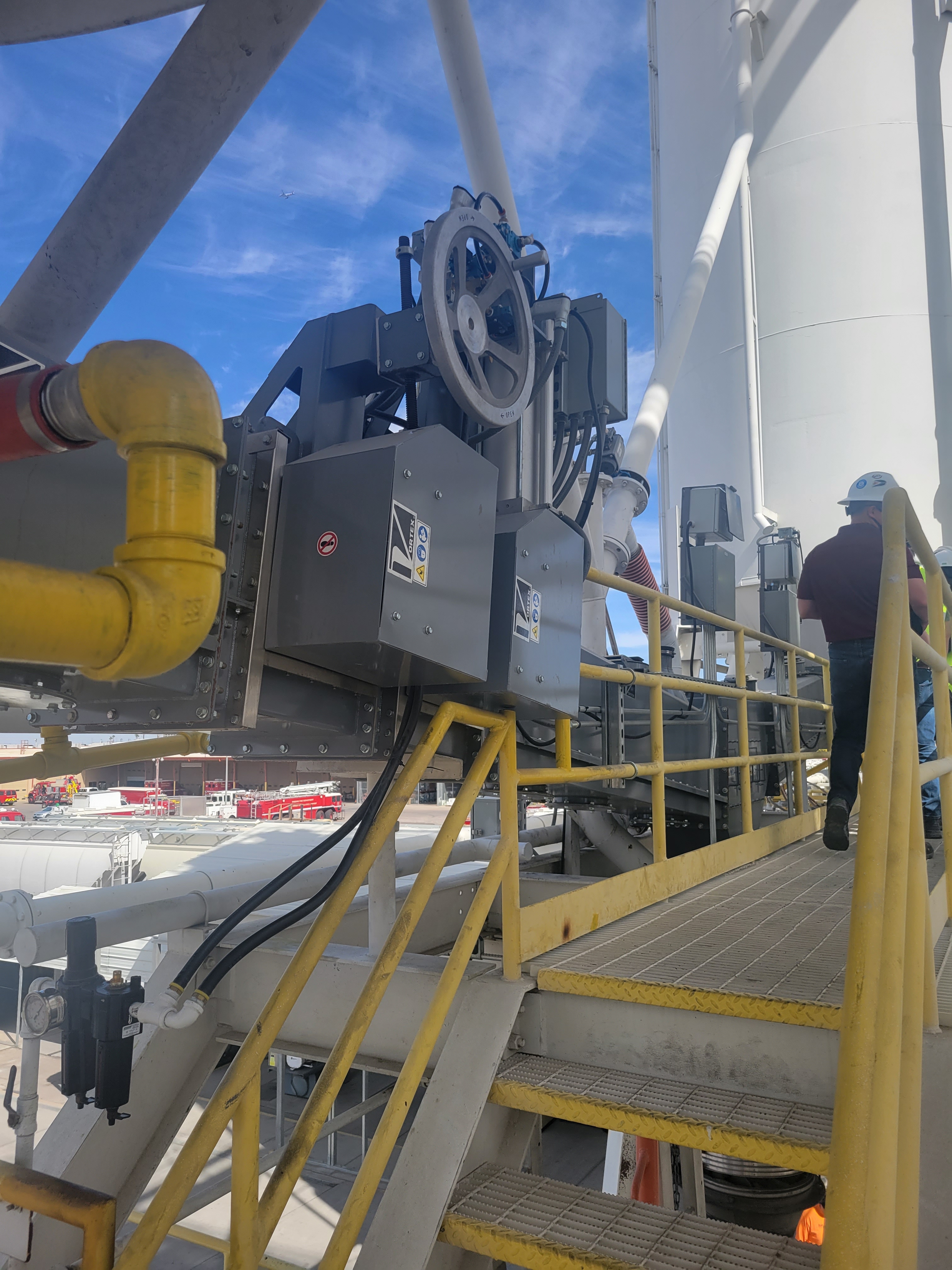
Case study: rail terminal
A rail terminal in the American southwest required three products from Vortex’s line of aerated conveying systems: The Vortex Aero-Slide conveyor, drum valve, and gate valve.
The conveyors offer many advantages for transporting lighter, dry bulk material. These advantages include infinite length, dust tight to atmosphere, no moving parts, subdued noise, cost effective energy consumption, simple installation, and maintenance expense savings.
This conveyor is equipped with a manually operated drum valve (maintenance valve), a pneumatically operated drum valve (material flow control valve), and a gate valve (shut off valve).
The drum valve features a rotating, cylindrical-shaped blade that incorporates a parabolic curve opening for more precise metering of material.
Conclusion
Maintenance is a necessity when handling dry bulk solid materials. When designing systems for these processes, certain factors must be taken into consideration to ease the frequency of required maintenance.
By sourcing products that require little maintenance, abrasion/wear concerns can be addressed and equipment can be serviced and maintained while in-line without having to interrupt operations, thus saving both time and money.
About the Author
In his third year with the company, Austin Anderson is the Content Writer for Vortex Global. He has created numerous case studies and written articles for a range of global publications sharing the successes Vortex products have experienced.


