


Client:
Quantity:
Size:
Application:
For nearly a decade, Ball Sales & Engineering – a Vortex equipment representative located in Huntington Beach, California, USA – has consulted with a roofing granules processor to provide them with bulk material handling solutions.
In that time, the client has consulted Ball on several occasions to consider revisions to their loadout process.
The Material
Roofing granules.
Material Properties:
- Bulk density: 90 lb/ftᶾ | 1,440 kg/mᶾ
- Temperature: 300° F | 150° C
- Other characteristics: Abrasive, fine material
The Process
In their current process, roofing granules are diverted from a silo into two chutes. At the discharge of each chute, an orifice plate is used to meter materials onto a belt conveyor. Both chutes discharge onto separate belt conveyors. The belt conveyors transport materials to a common loadout station.
The following will discuss projects where Vortex equipment was used to improve the client’s loadout process.
Project: Metering
In 2012, the equipment in question was the orifice plates. Rather than using orifice plates to meter materials at the discharge point, the client wanted to replace the slide gates beneath the silos to meter materials at the point of introduction. Doing so would eliminate the need for orifice plates at the discharge point.
After considering the application parameters, Ball recommended the Vortex Aggregate Gate as the ideal solution for this application. To proof out the new gate design in the application, only four Aggregate Gates were sourced to replace existing orifice plates.
Specifications:
- Size: 8 in | 205 mm (square)
- Gate body & material contact areas constructed from carbon steel.
- Blade constructed from 235 Brinell Hardness Number (BHN) abrasion-resistant steel.
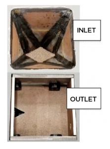
- Gate is equipped with a diamond-shaped Special Service Inlet & a V-notched blade (pictured). This modified configuration allows for more precise metering control as the gate closes.
- Bonnet seals to reduce material migration into the bonnet area & dusting to atmosphere.
- High temperature modification – Gate is rated for 250 F | 120 C (maximum) continuous service. Seals constructed from high heat rubber belting. Rollers constructed from hardened steel. Roller spacers & bonnet blade guides constructed from Nylon.
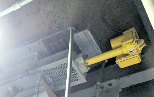
- Electric linear actuator – Selected for its smooth, slow-moving actuation to assist with metering accuracy. Actuator is equipped with a potentiometer to provide continuous variable feedback signals, directly proportional to the actuator’s stroke. This allows the actuator to be connected to control equipment, in order to provide positioning at any point along the actuator stroke – from fully retracted to fully extended.
Update
Once the gates were installed beneath the silos, they were successful in their metering responsibilities, but the client realized some material leakage past the blade upon closure. The client has since reverted to using orifice plates to meter materials at the discharge point. The Vortex Aggregate Gates are now used to shut-off silo discharge at the end of each cycle, and to isolate the silo so that it can be refilled between cycles.
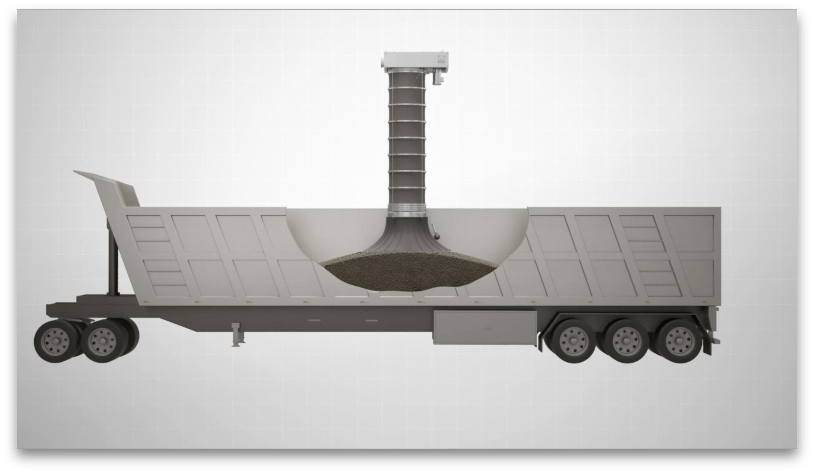
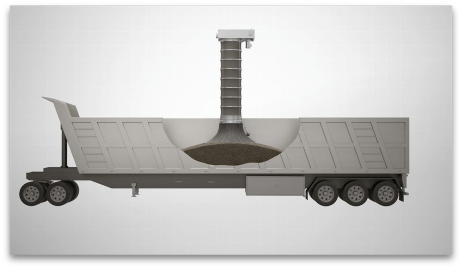
Project: Loading
In 2015, the process in question was the loadout station. The client was considering replacing their alternative loading spout with a Vortex Loading Spout.
After considering the application parameters, Ball recommended the following Vortex Loading Spout design.
Specifications:
- Intended for enclosed loading applications.
- Load rate capacity: 250 ftᶾ/min
- Outlet scavenger size: 14 in | 355 mm
- Travel distance: 4 ft | 1.2 m
- Stacking cones: constructed from polyurethane
- Equipped with an air pulse system. Once loadout is complete, the air pulse system is activated to purge materials and dusts remaining along the outer sleeve. This encourages those materials to clear from the sleeve to prevent cross contamination between trucks loading different color granules.
- Square-to-round transition piece – To transition down from the belt conveyor to the loading spout.
Update
Now entering its fourth year of service, this Vortex Loading Spout continues to satisfy the client’s performance expectations.
Project: Diverting
In 2016, the equipment in question was the diverters beneath each silo. Currently, the client is using bucket diverters worn beyond their useful life. In the replacement diverters, the client sought:
- A more robust design – To address significant wear and abrasion from the materials handled.
- Minimize material leakage to the opposite leg – Because flow rates out of the silo are greater than the flow rates metered at the orifice plates below, a standing column of material backs up through the chute and the diverter, up to the silo outlet. Because of this, the diverter must provide a positive seal across the opposite outlet leg, to prevent material leakage into the other chute.
With that, Ball recommended the Vortex Pivoting Chute Diverter as the ideal solution for this application.
The “pivoting chute” design was selected over a traditional “bucket” design because in bucket diverters, despite the inclusion of a bucket seal, material leakage to the opposite leg remains a concern when handling abrasive, fine materials. This is because of the bucket seal’s rigidity. As abrasive, fine materials are trapped between the bucket seal and the diverter body, they will “grind” against the two surfaces, creating wear to both the diverter body and the bucket seal. Over time, seal wear will become severe and material leakage to the opposite leg will occur.
Though the standard Vortex Pivoting Chute Diverter does not have internal seals, a modification to include internal seals was appropriate for this application. With a “pivoting chute” design, the chute has four solid sides which effectively guide material flow away from the sealing surfaces.
To proof out the new diverter design in the application, only one Pivoting Chute Diverter was sourced to replace an existing bucket diverter.
Specifications:
- Size: 8 in | 205 mm (square)
- Two-way, straight-leg diverting design.
- Double-acting air cylinder actuator. Air cylinder is equipped with a magnetic piston, to be used with magnetic reed switches for chute position indication.
- Inlet chute & pivoting chute constructed from chromium carbide.
- Outlet legs constructed from chromium carbide. Rest of diverter body constructed from painted carbon steel.
- The diverter’s removable access panel allows interior inspection and/or maintenance to be performed while the valve remains in-line.
- Lifting lugs for ease & safety during installation.
- Outlet legs taper down to 7 ½ in | 190 mm (square) size.
Results
Immediately, the client observed the Pivoting Chute Diverter performing better than the bucket diverters. In 2018, the client consulted Ball again to continue their retrofitting project to replace additional bucket diverters.
During the initial project in 2016, the client discovered they had made miscalculations in the dimensions for their downstream chute work. This impacted the performance of their Vortex Pivoting Chute Diverter. These miscalculations have since been corrected by sacrificing headroom in the downstream chute work.
To ensure the Pivoting Chute Diverter’s performance in this revised configuration, a second Pivoting Chute Diverter was ordered to be installed beneath another silo, replacing another bucket diverter. The second Pivoting Chute Diverter was designed to the same specifications, with the addition of a red arrow for chute position visual indication.


