


Client:
Quantity:
Size:
Application:
As featured in World Cement Magazine
by Kevin R. Peterson & Adam Schrage
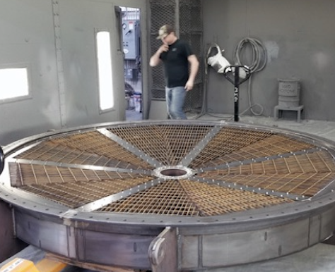
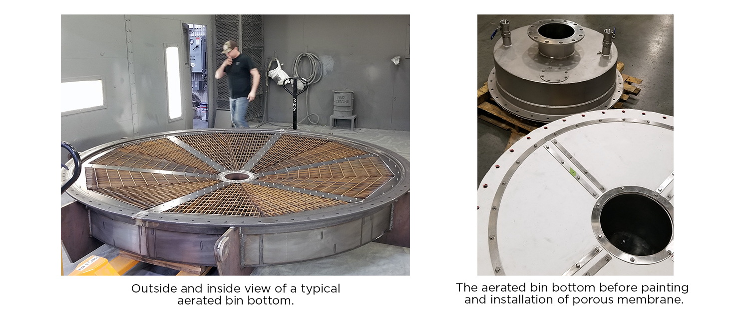
Aerated bin bottoms are used to move lighter weight dry bulk material that is capable of being fluidised. Fluidisation is the process in which air is passed through static, dry material, causing the material to acquire fluid-like characteristics. In its fluid-like state, the solid material flows better and is easier to handle.
An aerated bin bottom is installed at the bottom of a flat or conical-shaped silo or hopper. It contains an air chamber that is covered by a porous membrane. A fan or blower injects low pressure dry air (typically 6 psig/41 kPa) into the chamber. Air permeates the membrane, fluidising lightweight dry material within the silo. Aeration allows the material to flow out of the bin bottom discharge more consistently and at a higher rate.
Advantages of aerated bin bottoms
Aerated bin bottoms offer many advantages, including the following:
Material aeration within the bin eliminates the bridging and ratholing associated with bin storage. Bridging occurs when material forms a solid dome across the outlet of the bin and cannot flow properly. Ratholing is a channel that is formed through the material, which limits flow and discharge.
Aeration allows the material to flow at a much smaller angle of repose. The shallower angle equates to less head room required for the bin stackup. In addition, aeration promotes the consistent, continuous, and cost-effective discharge of material out of the bin.
Case study
A regional cement plant was having trouble in its truck loadout area. These issues created the following problems.
Loading times – The customer felt that it was taking too long to load each truck, which was evident from the complaints received from drivers.
Spout maintenance issues – Company maintenance personnel were spending valuable time fixing problems that centered around the telescoping loading spout. Cable wear and breakage was a major concern. This affected not only the budget for maintenance and repair parts, but also created problems with production and loading inefficiencies.
Dust collection – the dust collection system was inefficient in capturing and conveying dust that was created during the loading process.
Wasted product – Dust that escaped to the atmosphere and that was captured in the dust collector was unusable and became waste product.
Plant personnel were intent on finding solutions to the many issues they were experiencing. The bottom line was that they wanted to load trucks much quicker and experience less downtime due to equipment failures.
In researching companies that manufactured telescoping loading spouts, personnel became acquainted with Vortex Global. They were intrigued by the fact that this company’s spout offered a four cable hoist system with CNC-machined pulleys for minimal cable wear. Vortex also offered a spout filter.
The filter is installed above the spout. During the loading process, a fan located on the filter unit generates a slight vacuum within the spout. Dust created during the loading process is pulled up through the spout between the inner cones and the spout’s sleeve. The dust is temporarily trapped by pleated dust cartridges inside the filter. A pulse jet system intermittently frees the dust from the cartridges, causing it to mix with the material being loaded. Material is re-entrained with the load and sold as product rather than being disposed. The filter addresses air cleanliness as well as product waste.
The company contacted the local Vortex representative who, in turn, contacted Adam Schrage, Vortex’s Engineering Manager.
“This company already had some good ideas of what they needed to do to solve their loading problems,” Schrage recalls. “The major problem was that there was not enough room above the loading bay to install the equipment they needed.”
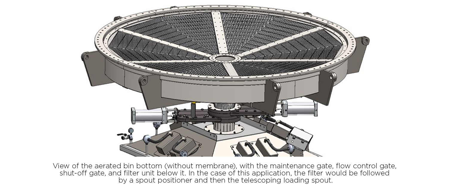
The bin used to store and feed material through the loading spouts had a cone bottom with a very steep angle of repose. Unfortunately, this took up a lot of vertical space. Vortex broached the idea of cutting off the bottom of the bin to gain additional height. An aerated bin bottom would be custom manufactured and installed at the bottom of the bin. Installing the bin bottom would also allow additional room within the equipment stackup. It was then determined that placing a filter unit in the stackup would offer faster loading rates, while also controlling the dust.
The company liked this idea and placed an order for a telescoping loading spout, dual axis spout positioner, filter unit, and aerated bin bottom. “The bin bottom was actually the key to making this whole project happen,” said Schrage.
The bin bottom was 3.55 m (140 in.) dia. It weighed 2948 kg (6500 lb) and was installed in an area that had a very tight footprint.
“Before the completion of this project, it was taking 5 to 6 min. to load a truck – if there was no repositioning or other problems,” said Schrage. “After the installation, trucks did not have to reposition and they took less than 3 min. to load.”
Savings created by the project
The project led to the following efficiencies:
Faster loading time – The plant was able to load almost twice as many trucks during the day.
Capture of material – Dust was re-entrained to the load, meaning the company could be paid for the material rather than disposing of it. This also created a safer/healthier environment.
Cost savings – Money was saved from reduced maintenance and increased production.
Things to consider
When considering the use and installation of an aerated bin bottom, the following elements should be kept in mind:
Material handled – The material handled should be dry (less than 1% moisture) and fluidisable. Typically, the material would be in powder form and would be able to pass through a 20 mesh screen. The types of material handled normally include bentonite, bauxite, carbon black, cement, clay, flour, flyash, lime, potash, powder, resin, silica, soda ash, and starch, to name a few.
Desired flow rate – Flow rate determines the size of the bin bottom and the discharge opening.
Clean dry air – Aerated bin bottoms typically require a positive displacement blower that can supply air at 6 psig. The air must be clean and dry.
Air pads – Depending on the size of the bin, air pads may be required on the side of the bin and/or above the bin bottom.
Multiple discharge points – Additional discharge points may be included on the bottom or the side of the bin bottom. This becomes and important space saver when one bin is utilised to feed different areas or processes.
Consulting a system analyst or engineer is recommended before moving forward with similar projects. All Vortex bin bottoms are custom designed to match the existing silo and address end-user loading requirements.
About the authors
Now in his 24th year with the company, Kevin R. Peterson is the Business Development Director for Vortex Global. He is a board member of the Industrial Minerals Association of North America, and has created and shared hundreds of case studies, as well as writing numerous articles.
Adam Schrage is the Engineering Manager for Vortex Loading Systems. Throughout his career, Adam has acquired practical experience through the design and implementation of dry bulk material loading systems. A Michigan native, he engineers individual projects and advises Vortex customers throughout North America.


