


Client:
Quantity:
Size:
Application:
For both the A-Style and the K-Style diverter design option, the primary responsibility is to divert material from a single source toward either of two locations. However, the application benefits for each design vary from one another.
What do these diverters have in common?
In gravity flow applications, certain materials achieve optimal flow rates if they are processed through a diverter with steeper, more dramatic outlet leg angles. Steeper angles are used to flow heavier, denser materials – such as aggregates. Steep angles reduce the likelihood of in-line material build-up or material plugs, which can otherwise create the need for maintenance.
If a diverter has more subtle angles, material velocity will slow, causing materials to drag along the bottom of the valve as they flow. With steeper outlet angles, material is able to suspend and flow more freely through the channel. As a result, the valve makes little contact with materials and thus, is subjected to less wear and abrasion, which furthers the valve’s useful life.
A common misconception of diverter valves is that the blade can be shifted “on the fly” to divert material toward different locations as material flows through it. While the equipment does have the mechanical capabilities to do so, actuating a diverter in a continuous stream of material is harmful to the diverter’s functionality. As the diverter actuates, materials can pack in areas where the blade comes in contact with the diverter body. Over time, material build-up may occur at these points, preventing the blade from properly sealing and allowing material leakage through the diverter.
Should a diverter need to be shifted to redirect material toward the other destination, a slide gate can be installed above the diverter to shut off material flow prior to re-positioning the blade.
But First, a Few Definitions...
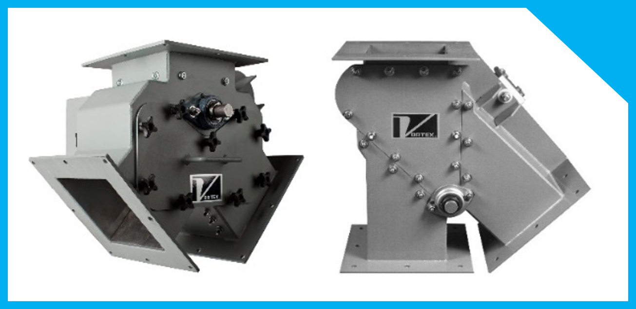
- A-Style Diverter: A diverter with two, symmetrical legs of equal angle. When installed into a system, the diverter will appear identical in shape to the capital-letter A.

- K-Style Diverter: A diverter similar in shape to the bottom portion of a capital-letter K. When installed into a system, the diverter features one vertical leg and an angled leg.

- Straight Leg: The straight, vertical leg on a K-Style diverter design.

- Off Leg: This concept is often misperceived. Some believe the off leg is simply the diverter leg that is turned “off” from the material flow stream. By this definition, the off leg would be subject to change almost continuously. The true definition of the off leg is: The angled leg on the K-Style diverter design, which normally experiences less material flow activity.

Intended Uses
For many applications, it is appropriate to source an A-Style diverter if the manufacturing process requires diversion of similar material quantities toward each destination. Oppositely, a K-Style diverter is appropriate if a process requires most of the material to be routed toward one destination. In typical applications, that material is routed directly through the diverter’s straight leg and will flow upwards of 70 – 90 percent of the materials handled, with the off leg handling the difference.
Concerns for Abrasion

With A-Style diverters, abrasion and wear can be a concern because as materials flow through the inlet, they can make direct impact where the legs meet.
With the K-Style option, material impact where the legs meet is minimized by creating a straight-through channel. Although the K-Style reduces abrasion where the legs meet, it leaves the straight leg susceptible to wear due to its more regular use.
Many diverter valve designs feature a flat blade that is thinner than the blade shaft. When handling abrasive materials, this design can create two potential problems. First, over time, the material can prematurely wear the blade shaft itself. Second, when the blade is in position to divert materials, “ski jumping” of material may occur. Ski jumping is the tendency for material to roll down the blade, hit the crown of the blade shaft, and “ramp” into the sides of the diverter. This will eventually wear a hole through the body of the diverter.
Both the A-Style and the K-Style designs may be modified to address abrasion from the material handled.
Features to Protect Against Abrasion

Blade Shaft Protection
In Vortex flap-style diverters, the problems associated with blade shaft wear and ski jumping are addressed by using an “A” Style Blade configuration to protect the blade shaft (Figure 1). This design tapers at the blade’s leading edge, but is enlarged at the blade shaft so that the crown is minimally exposed. This design better protects the blade shaft and diminishes the effects of ski jumping.
Vortex diverters also feature a live-loaded polymer seal beneath the blade shaft (Figure 2), which serves as a barrier to prevent material packing, material spoilage or infestation (in the case of handling food-grade product), or migration of material to the opposite leg.
Abrasion-Resistant Liners
Depending on material characteristics, Vortex diverters can be equipped with a replaceable 400 BHN abrasion-resistant carbon steel blade, and with replaceable 400 BHN abrasion-resistant carbon steel liners along the diverter’s inner walls to protect against abrasion. In extreme cases, liners may even be constructed from chromium carbide.

In some material handling applications, replaceable UHMW liners can instead be installed at the blade and along the diverter’s inner walls to protect against abrasion. UHMW is a hard polymer that, in specific applications, has been found to be more effective than carbon steel because it allows materials to “bounce” off of the liners. UHMW is also inherently slick, which allows some materials to achieve more optimal flow rates.
In either case, from a cost-benefit standpoint, abrasion-resistant liners are of utmost importance to prolonging a diverter valve’s useful life because they are the difference between materials abrading upon replaceable parts, or materials abrading through the diverter body and creating need for full valve replacement.
Which Design is Best?
Because dry bulk material characteristics can be quite different from one another, application-specific considerations must be made when selecting equipment to handle them. Neither the A-Style nor K-Style diverter design can be declared universally “better” than the other.
It is important to consult with industry experts to analyze your unique dry bulk material handling application and select the most appropriate diverter valve design based on features, benefits, functionality, and overall suitability for use in your system.


